
Materiale Necessario per la realizzazione
- 1x Arduino Mega 2560 R3
- 1x fgMega Shield (https://sites.google.com/site/pegasocubeproject/home/fgmega-shield)
- 1x relais module with 4 relais
- 1x Nextion HMI Display 2.8″
- 1x DHT11 temperature and Humidity sensor
- 1x Light sensor
- 1x ESP-8266 (ESP-01)
- 1x RTC Clock (DS1302 or DS1307)
- 1x SD or MicroSD Card module
- 1x Power supply with dual voltage (dc 9 + dc5)
- 1x C14 power connector
- 1x Power Switch fo AC
- 1x 12mm 4 Pin Male & Female Aviation Plug Wire Panel Connector GX12
Step for building (working progress…)
|
1) Print bottom case
|
 |
|
|
 |
|
 |
||
| 4) Print “Mammut” support |
 |
|
|
5) create a PCB Shield for Arduino Mega
or buy my fgMega Shield with or without parts
|
 |
|
|
6) Mount the Arduino Board to the botton case
7) Mount the PCB Shield over the arduino board
8) Install the Relay Board (I have used 2×2 reails module)
9) Mount the C14 Power Plug
10) Mount the Power Switch
|
 |
|
| 11) Prepare the Mammut Support and install into the 4 Mammut or similar connector
12) Mount the “Mammut Support” onto Reails Module (I have fixed it with a double side Adhesive) |
 |
|
| 13) Install the Power Supply (+9V and +5V)
14) Install SD card Reader on the left on Power Module |
 |
|
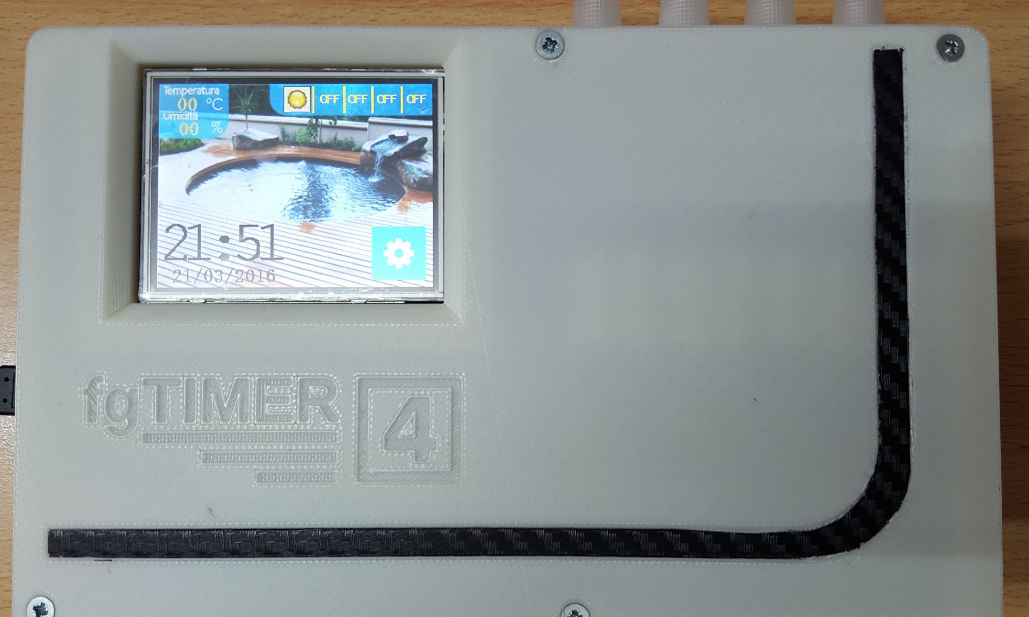
| 15) Install the Nextion Display on case
16) connect Nextion Display to PCB (link)
|
 |
|
| 17) Connect the External Sensors |

|
|
|
18) Upload the nextion HMI files thru Nextion editor (connect a USB to Serial adapter to specific ports on fgMega Shield, remember to switch off the connection using dip switch)
|
||
|
||
|
20) Connect a ESP-01 WIFI Adapter (link)
|
||
|
21) Connect the Relais Module (link), remember to use an external power adapter for Relais Module (use a 5v)
|
||
|
22) Upload the arduino project
|
||
|
under contruction
23) Prepare the external sensors case and cabling it by the following schema24)
|
||
